cream separator manual
Cream separators‚ vital for dairy processing‚ efficiently divide milk into cream and skim milk. These machines‚ ranging from manual to industrial‚ support diverse production scales.
What is a Cream Separator?
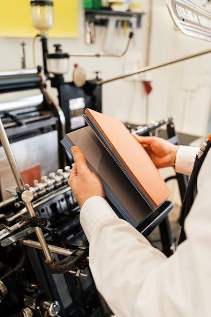
A cream separator is a mechanical device designed to exploit the difference in density between cream and skim milk to effectively separate them. Historically‚ this process was laboriously done by allowing milk to sit and cream to rise – a time-consuming and inefficient method. Manual cream separators‚ representing an early advancement‚ utilize centrifugal force achieved through hand-cranking.
These machines feature a rotating drum where milk is introduced‚ causing the heavier skim milk to move outwards while the lighter cream accumulates towards the center. They are compact and efficient for low-volume production‚ maintaining product quality with minimal maintenance. While requiring physical effort‚ manual separators offer a reliable solution for small-scale creameries and farmsteads‚ proving to be durable workhorses with simple mechanical designs.
Historical Overview of Cream Separation
Before mechanized solutions‚ cream separation was a tedious‚ gravity-based process. Farmers relied on letting milk stand‚ allowing cream to naturally rise to the surface – a slow and inconsistent method. The late 19th century witnessed the advent of manual cream separators‚ revolutionizing dairy practices. These early machines‚ driven by hand-cranking‚ introduced centrifugal force for faster‚ more efficient separation.
This innovation dramatically reduced labor and improved cream quality. The simple mechanical design of these separators contributed to their longevity‚ often lasting for decades with proper care. While later superseded by electric and engine-powered models‚ the manual separator laid the foundation for modern dairy processing‚ particularly benefiting small-scale operations and farmsteads seeking increased productivity.

Types of Cream Separators
Manual cream separators utilize hand-cranking to generate centrifugal force. They are compact‚ efficient for low-volume production‚ and require minimal maintenance for precise separation.
Manual Cream Separators
Manual cream separators represent the earliest form of this essential dairy technology. These devices rely on human power – typically a hand crank – to spin a drum and generate the centrifugal force necessary for separating cream from milk. Their simplicity is a key advantage‚ making them suitable for small-scale operations like farmsteads and artisanal creameries where electricity might be unavailable or impractical.
Despite their manual operation‚ these separators are remarkably effective. They boast a durable design‚ often lasting for decades with proper care. The mechanical simplicity translates to fewer potential points of failure‚ ensuring reliable performance. While requiring more physical effort than electric or engine-powered models‚ manual separators offer a cost-effective and sustainable solution for smaller dairy needs‚ maintaining high product quality with minimal maintenance.
Electric Cream Separators
Electric cream separators mark a significant advancement over manual models‚ offering increased consistency and capacity. Powered by an electric motor‚ they eliminate the need for manual cranking‚ streamlining the separation process and reducing operator fatigue. This makes them ideal for operations requiring higher throughput‚ such as growing dairies or small-scale commercial producers.
These separators maintain the core principle of centrifugal force but achieve it through automated rotation. Their design often incorporates features for precise control over cream consistency‚ adjustable through settings that influence the separation process. Electric models represent a modern approach‚ balancing efficiency with reliability. They are built to last‚ offering consistent daily use and reducing the labor demands associated with traditional manual separation techniques.
Engine-Powered Cream Separators
Engine-powered cream separators provide a robust solution for locations lacking consistent access to electricity. Utilizing gasoline or diesel engines‚ these machines deliver the power needed for efficient cream separation independent of electrical grids. This makes them particularly valuable for farmsteads or remote dairy operations where electrical infrastructure is limited or unreliable.
Like their electric counterparts‚ engine-powered separators leverage centrifugal force for separation‚ but with the added benefit of portability and self-sufficiency. They often share similar durability characteristics‚ built as reliable workhorses for consistent daily use. While potentially requiring more maintenance than electric models due to the engine component‚ they offer a vital solution for maintaining dairy production in challenging environments‚ mirroring the efficiency of electric options.

Key Components of a Cream Separator
Essential components include the drum (centrifugal drum)‚ a disc stack within‚ and a feed system. These work together to efficiently separate cream from milk.
The Drum (Centrifugal Drum)
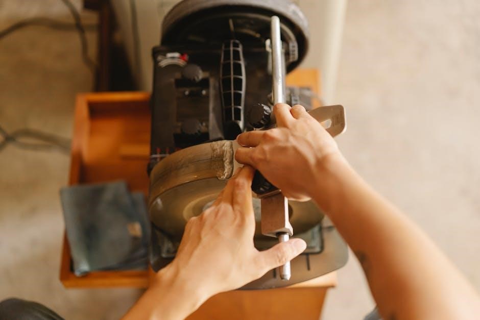
The drum is the heart of any cream separator‚ functioning as the central chamber for centrifugal separation. It spins rapidly‚ creating the force necessary to separate milk components based on density. Manual separators feature a hand-cranked drum‚ while electric and engine-powered models utilize motors for consistent rotation.
Inside the drum resides the crucial disc stack‚ comprised of numerous conical discs stacked closely together. Milk enters the drum and flows through these narrow channels‚ maximizing surface area for efficient separation. The drum’s design‚ with discs angled at 45 to 60 degrees‚ creates a separation channel of 0.4 to 2.0 mm. This precise geometry is vital for achieving clean separation of cream and skim milk‚ ensuring optimal product quality.
Disc Stack
The disc stack within a cream separator’s drum is a marvel of engineering‚ crucial for efficient separation. Composed of up to 120 conical discs‚ these are meticulously stacked with a narrow gap – typically 0.4 to 2.0 mm – creating separation channels. Milk is introduced near the inner edge of this stack‚ then flows upwards through these channels.
This design maximizes the surface area for separation‚ allowing the centrifugal force to effectively differentiate between cream and skim milk. In manual separators‚ maintaining the integrity of this stack is paramount. Proper cleaning and careful handling prevent damage to the discs‚ ensuring consistent performance. The precise angle (45-60 degrees) and spacing are key to optimal separation‚ influencing both cream quality and throughput.
Feed System
The feed system in a manual cream separator is deceptively simple yet critical for consistent operation. It typically involves a hopper or tank where raw milk is initially held‚ then a valve or flow regulator controlling the milk’s entry into the separator. Maintaining a steady‚ controlled flow is essential; fluctuations can disrupt the separation process and reduce efficiency.
Users must ensure the milk is pre-filtered to remove larger particles that could clog the delicate disc stack. The feed system’s design directly impacts the load on the drum‚ influencing separation quality. Careful monitoring of the feed rate‚ adjusted based on milk temperature and fat content‚ is vital for optimal performance in these manually operated machines.

Operating a Cream Separator
Manual cream separators require consistent hand-cranking to maintain drum speed for effective separation. Adjusting the flow screw impacts cream consistency‚ avoiding thread over-turning.
Initial Setup and Preparation
Before operating a manual cream separator‚ ensure a stable‚ level surface for placement. Thoroughly inspect all components – the drum‚ disc stack‚ feed system‚ and collection outlets – for cleanliness and proper assembly. Verify the drum is securely fastened and rotates freely.
Pre-warming the milk to around 90-100°F (32-38°C) enhances separation efficiency. Gently pour the warmed milk into the feed system‚ avoiding overfilling. Begin cranking the handle at a consistent‚ moderate pace to initiate drum rotation.
Observe the initial separation process‚ noting the flow of cream and skim milk. Adjust the speed slightly if needed‚ maintaining a smooth and even rotation. Proper preparation is crucial for optimal performance and consistent results with your manual separator.
Adjusting Cream Consistency
Fine-tuning cream consistency in a manual separator involves careful adjustment of the separating plate screw. If the cream is too thick‚ indicating excessive fat content‚ turn the screw clockwise – but cautiously‚ avoiding over-tightening. Conversely‚ watery cream suggests insufficient fat‚ requiring a counterclockwise turn.
Remember‚ even a single turn can significantly impact the separation. Monitor the cream’s texture after each minor adjustment. The goal is to achieve the desired richness and viscosity for your specific application.
Pay close attention to the screw’s movement‚ ensuring it doesn’t overtighten and damage the threading. Precise adjustments yield optimal cream quality and minimize waste.
Troubleshooting Watery Cream
Watery cream from a manual separator typically indicates insufficient separation‚ often resolved by adjusting the separating plate. The primary solution is to turn the adjustment screw counterclockwise‚ incrementally. A single turn is usually sufficient to increase fat retention in the cream.
However‚ exercise caution! Avoid forceful turning to prevent damage to the screw threads or the drum plate holder. Observe the cream’s consistency after each adjustment‚ allowing time for the separator to stabilize.
Ensure the screw doesn’t reach its stop on the threaded surface. Consistent monitoring and gentle adjustments are key to achieving the desired cream thickness.

Maintenance and Care
Regular cleaning and maintenance are crucial for manual cream separators‚ ensuring longevity and optimal performance. Drum components require careful attention and upkeep.
Drum Components Maintenance

Maintaining the drum is paramount for a manual cream separator’s efficiency. Centrifuges utilize a disc stack – up to 120 discs angled at 45-60 degrees‚ separated by 0.4-2.0mm gaps. Milk enters the inner edge of this stack.
Regularly inspect these discs for wear or damage‚ as they are critical for separation. Ensure the gaps remain clear of obstructions. The drum itself should be thoroughly cleaned after each use to prevent milk solids from building up and hindering performance. Pay close attention to the threaded surfaces during cleaning‚ avoiding forceful actions that could damage them. Proper drum maintenance directly translates to consistent cream quality and extended machine lifespan.

Cleaning Procedures
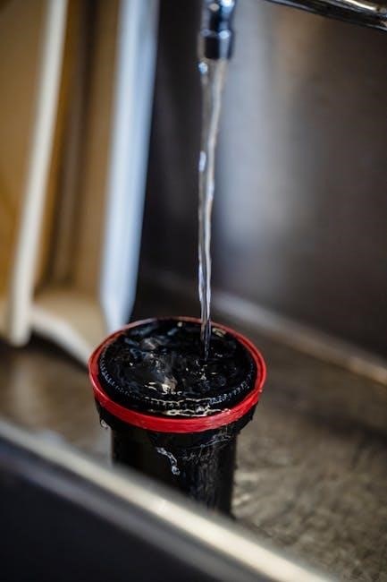
Thorough cleaning after each use is crucial for a manual cream separator. Disassemble the drum carefully‚ separating all components – discs‚ bowl‚ and cap. Wash each part with warm‚ clean water and a mild detergent. Avoid abrasive cleaners that could scratch the surfaces.
Pay special attention to the disc stack‚ ensuring all milk residue is removed from the narrow channels. Rinse all parts thoroughly to eliminate any detergent traces. Before reassembling‚ inspect for any damage or wear. A clean separator ensures hygienic operation and prevents contamination‚ preserving cream quality and extending the machine’s lifespan. Regular‚ diligent cleaning is a simple yet vital maintenance step.
Long-Term Storage

Proper storage is essential when a manual cream separator isn’t in regular use. After a thorough cleaning and drying – ensuring no moisture remains – lightly coat all metal parts with food-grade mineral oil. This prevents rust and corrosion during prolonged inactivity.
Store the disassembled components in a clean‚ dry‚ and pest-free environment. A sealed container or plastic bag can offer additional protection. Avoid storing in damp basements or outdoor sheds. Periodically check the stored parts for any signs of corrosion. Before resuming use‚ re-clean and re-oil as needed‚ guaranteeing optimal performance and hygiene. Careful storage safeguards your investment.

Durability and Lifespan
Manual cream separators‚ with their simple mechanical design‚ are remarkably durable‚ often lasting for decades with consistent‚ proper maintenance and careful use.
Factors Affecting Separator Lifespan
Manual cream separator longevity hinges on diligent care. Regular cleaning prevents milk solids buildup‚ crucial for smooth operation and preventing component wear. The quality of initial construction significantly impacts lifespan; robust materials withstand years of use.
Frequency of use also plays a role – consistent daily operation may necessitate more frequent maintenance than occasional farmstead use. Proper lubrication of moving parts minimizes friction and extends component life. Avoiding overfilling or forcing operation prevents undue stress on the drum and internal mechanisms.
Finally‚ environmental factors like temperature and humidity can contribute to corrosion if the separator isn’t stored correctly. Careful handling and avoiding impacts protect against physical damage‚ ensuring decades of reliable service with consistent attention.
Repair and Replacement Parts
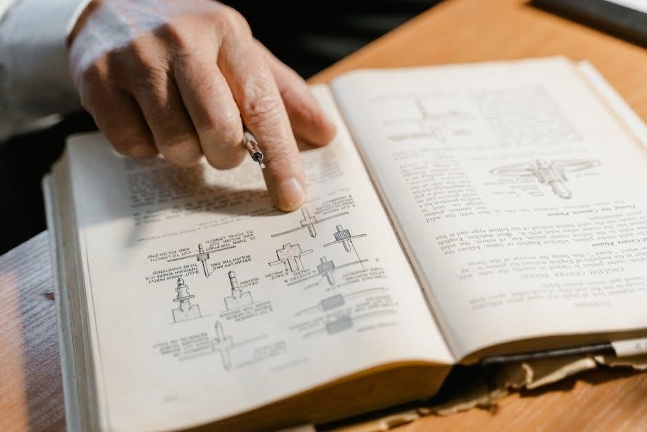
Manual cream separators‚ with their simpler design‚ often allow for straightforward repairs. Common replacement parts include rubber gaskets‚ bearing sets‚ and occasionally‚ individual disc stack components. Finding original parts for older models can be challenging‚ necessitating resourceful sourcing from specialized suppliers or vintage machinery communities.
Repairing a manual separator typically involves disassembly‚ cleaning‚ inspection for wear‚ and replacement of damaged parts. Detailed manuals‚ if available‚ are invaluable. Skilled handymen or those familiar with mechanical systems can often handle repairs independently.
However‚ significant drum damage or irreparable component failure might warrant professional assessment. Maintaining a small stock of frequently replaced parts‚ like gaskets‚ minimizes downtime and ensures continued operation. Prioritizing preventative maintenance reduces the need for extensive repairs overall.

Applications and Scale
Manual cream separators suit small-scale dairies and farmsteads‚ offering a compact‚ efficient solution for low-volume production while ensuring high product quality.
Small-Scale Dairies & Farmsteads
Manual cream separators are exceptionally well-suited for the unique demands of small-scale dairies and farmsteads. Their inherent simplicity translates to minimal maintenance requirements‚ a crucial benefit for operations where specialized technical expertise might be limited. These machines offer a cost-effective entry point into cream production‚ avoiding the substantial investment associated with electric or engine-powered alternatives.
The compact design of manual separators makes them ideal for smaller processing spaces‚ commonly found on farms. Despite their manual operation‚ they consistently deliver precise cream separation‚ upholding high product quality essential for artisanal dairy producers. Their robust construction ensures decades of reliable service with proper care‚ functioning as dependable workhorses for daily use‚ perfectly aligning with the needs of these smaller-scale operations.
Industrial Dairy Production
While manual cream separators historically played a role‚ industrial dairy production overwhelmingly relies on electric or engine-powered separators for their capacity and consistency. Manual methods simply cannot match the throughput demands of large-scale operations. However‚ understanding the principles of separation – initially refined through manual machines – remains foundational.
The transition to automated systems represents a significant leap in efficiency. Modern separators handle vast volumes of milk‚ ensuring continuous and precise cream separation. Though manual separators aren’t directly employed in large facilities‚ their basic design informs the functionality of automated disc-stack centrifuges. The core principle of centrifugal force remains constant‚ albeit implemented with advanced engineering for maximized output and minimal labor.